Detailed guide to the OTDR
Here we want to share how to better use the OTDR with you.OTDR mainly measurement content includes:
● The location (distance) of the event, the result of the link, or the break;
● Optical fiber attenuation coefficient in link;
● Loss of a single event (such as a flat joint or bend), or total loss of a link end to end;
● An event such as connector reflection amplitude;
● The cumulative loss of an event can be automatically measured.
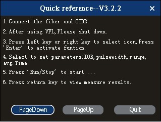
After starting up, first enter the LOGO page of OTDR and then enter the main page.
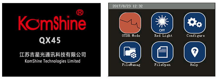
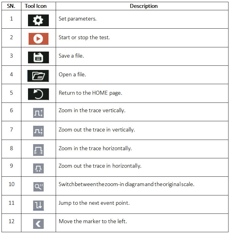
Komshine QX45 has 3.5in touch screen,the key and function are as follows:
OTDR Parameter Setup Operations
Accurate parameters settings are mandatory for accurate measurement of an optical fiber. Therefore, before using the OTDR, you need to set parameters as required. The following describes who to set parameters in details.
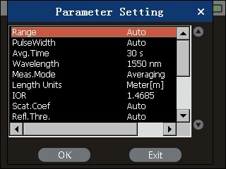
You can set parameters by using keys on the keypad or by tapping the touch screen. You can press [▲] or [▼] to select the parameter setup icon, and press [Enter] to enter or [ESC] to exit from the parameter setup page.
Alternatively, you can tap the corresponding items on the touch screen to set parameters. The setup operations on the touch screen have the same effects as keypad operations.
Setting the Distance Range
Generally, the distance range is set based on the actual length of the optical fiber. In this way, the measurement accuracy can be ensured.On the parameter setup page, press [▲] or [▼] to select Distance range. Press [Enter] to enter or [ESC] to exit from the distance range setup page.
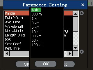
Press [▲] or [▼] to select an appropriate distance range, and press [Enter] to make the setting effective.
Setting the Pulse Width
Selection of a pulse width affects the dynamic range and resolution of the test trace. If the narrow pulse width test is selected, a higher distance resolution and a smaller dead zone can be achieved, but the dynamic range decreases. In contrast, if the broad width test is selected, a longer distance of optical fiber can be tested, but the distance resolution is lower and the dead zone is larger. Therefore, users need to balance between the dynamic range and the dead zone.
Different pulse width options are provided as reference, depending on the selected distance range.
On the parameter setup page, press [▲] or [▼] to select Pulse width. Press [Enter] to enter or [ESC] to exit from the pulse width setup page.
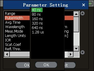
Press [▲] or [▼] to select a pulse width as required, and press [Enter] to make the setting effective.
Setting the Measurement Avg. Time
The measurement Avg. Time directly affects the signal to noise ratio (SNR) of the trace. If a measurement Avg. Time is longer, the SNR becomes higher and a larger dynamic range can be achieved. Therefore, when measuring a long-distance optical fiber or viewing remote-end events, select a longer measurement Avg. Time whenever possible.
On the parameter setup page, press [▲] or [▼] to select Measurement Avg. Time. Press [Enter] to enter or [ESC] to exit from the measurement Avg. Time setup page.
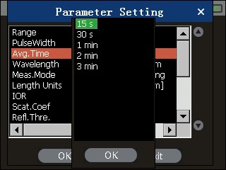
Press [▲] or [▼] to select an Avg. Time as required, and press [Enter] to make the setting effective.
Setting the Laser Wavelength
On the parameter setup page, press [▲] or [▼] to select Laser wavelength. Press [Enter] to enter or [ESC] to exit from the laser wavelength setup page, as shown in Figure 3-14.
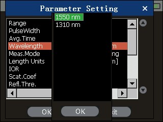
Figure 3-14 Setting the laser wavelength
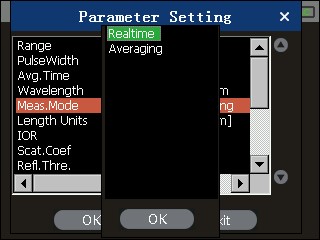
Setting the Measurement Mode
Two measurement modes are available: real-time and average.
In real-time mode, the OTDR tests the connection status of the external optical fiber in real time and update the test trace in time. In real-time mode, the measurement stops only when you press [Run/Stop]; otherwise, the measurement goes on an on. In average mode, the OTDR accumulates and averages the measurement data based on the selected measurement duration. When the measurement time is equal to or longer than the measurement duration set by the user, the current measurement stops and the measurement result is displayed. Generally, you can select the average mode for measurement.
On the parameter setup page, press [▲] or [▼] to select Measurement mode. Press [Enter] to enter or [ESC] to exit from the measurement mode setup page, as shown in Figure 3-15.
Setting the Length unit
On the parameter setup page, the length unit is set to m by default.
Setting the Reflection Rate
The reflection rate of an optical fiber affects the transmission speed of the light on the optical fiber. Therefore, setting of the reflection rate directly affects the accuracy of measured distance. Generally, the reflection rate of an optical fiber is provided by the manufacturer of the optical fiber. It can be set to any value between 1.0 and 2.0. The value has a precision of four decimal places.
On the parameter setup page, press [▲] or [▼] to select Reflection rate. Press [Enter] to enter or [ESC] to exit from the reflection rate setup page, as shown in Figure 3-16.
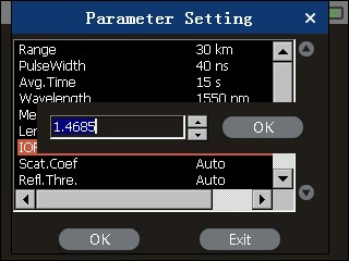
Press [◀ ] or [▶]to select the digit to be modified, and press [▲] or [▼] to modify the value of the selected digit. After modification is completed, press [Enter] to make the setting effective and press [ESC] from the setup page.
Setting the End Threshold
This threshold is the fiber end threshold. If the end threshold is set to 3.0 dB, the first event with the insertion loss equal to or higher than 3.0 dB on the test trace is regarded as the end of the optical fiber.
On the parameter setup page, press [▲] or [▼] to select End threshold. Press [Enter] to enter the end threshold setup page, as shown in Figure 3-17.
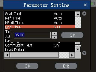
Press [◀ ] or [▶]to select the digit to be modified, and press [▲] or [▼] to modify the value of the selected digit. After modification is completed, press [Enter] to make the setting effective and press [ESC] to exit from the setup page.
The default value of End threshold is 5.00 dB.
Setting the Time
The time setup menu is used to modify the system time of the OTDR.
On the parameter setup page, press [▲] or [▼] to select Time. Press [Enter] to enter or [ESC] to exit from the time setup page, as shown in Figure 3-18.
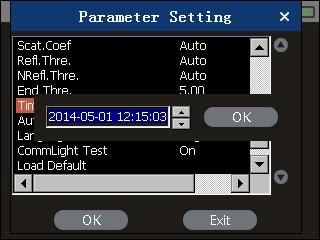
Figure 3-18 Setting the time
Press [◀ ] or [▶]to select the digit to be modified, and press [▲] or [▼] to modify the value of the selected digit. After modification is completed, press [Enter] to make the setting effective.
Recovering the Default Settings
You can recover the factory settings of some parameters on the OTDR. These parameters include Distance range, Pulse width, Measurement duration, Reflection rate, and End threshold. On the parameter setup page, press [▲] or [▼] to select Default. Press [Enter] to enter or [ESC] to exit from the page for recovering default settings, as shown in Figure 3-19.
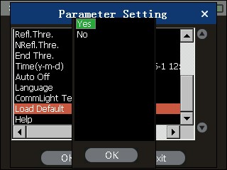
Press [▲] or [▼] to select Yes or No, and press [Enter] to make the setting effective.
Help
You can obtain the online help from the Help menu.
OTDR trace
Connect the optical fiber to the optical outlet of OTDR without any tools, and clean the connector before connecting. When we do not know the length of the fiber, we can use AuTo automatic measurement function, and QX45 OTDR can automatically select the appropriate range of distance for the fiber under test.
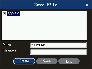
Star testing, and OTDR can obtain a complete trace through a measurement process. When the test is finished, save the trace; you can name the file yourself.
Storage trace upload
You can use a USB flash drive or an SD card to upload a stored trace to a PC. On the PC, you can use the analysis software to perform more flexible operations on the trace.


